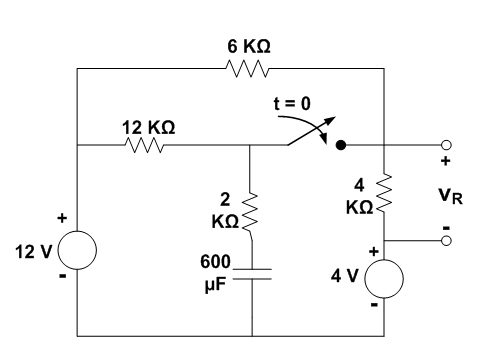
Question (1)
a)Using the “Laplace Transform”, derive an expression for VR(t) shown in figure for
t> 0 and sketch your results in volts against time in seconds .
b)Calculate the initial and steady-state values for VR(t) and check your results using
the initial and final value theorems .
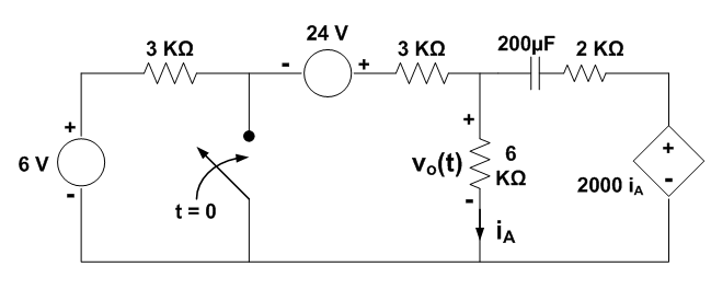
Question (2)
a)Using the “Laplace Transform”, derive an expression for vo(t) shown in figure for
t> 0 and sketch your results in volts against time in seconds .
b)Calculate the initial and steady-state values for vo(t) and check your results using
the initial and final value theorems .
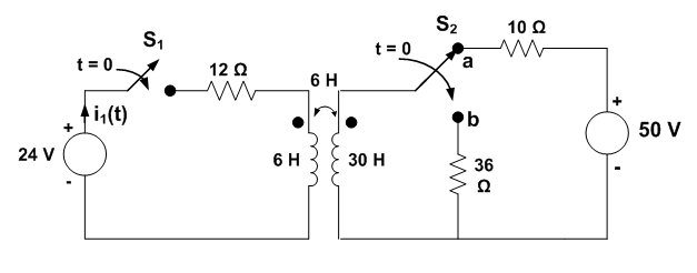
Question (3)
In the circuit shown in figure, switch S1 closes at t=0 and instantaneously switch S2 moves from position a to position b :
i)Using the “Laplace Transform Technique”, derive an expression for the current i1(t)
fort > 0 .
ii)Calculate the initial and steady-state values of the current i1(t) and check your
results using the initial and final value theorems .
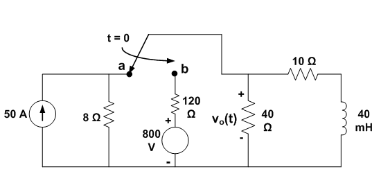
Question (4)
The switch in the circuit shown in figure has been in position a for a long time. At t=0, it moves to position b. Using the “Laplace Transform”, derive an expression for the voltage vo(t) for t > 0 . Calculate its initial and steady-state values using the initial and final value theorems.
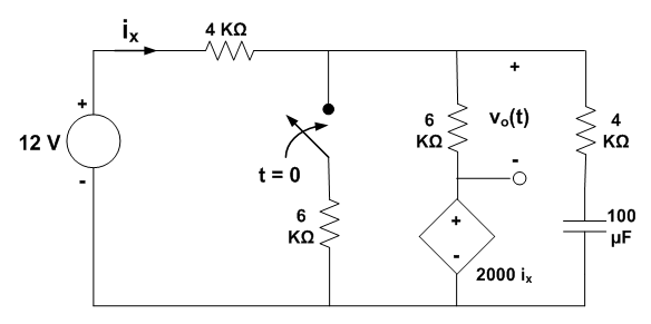
Question (5)
The switch in the circuit shown in figure has been opened a long time before closing at t=0. Using the “Laplace Transform”, derive an expression for the voltage vo(t) for t>0.Calculate its initial and steady-state values and check your results using the initial and final value theorems.
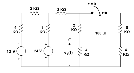
Question (6)
The switch in the circuit shown in figure has been closed for a long time before opening at t=0:
a)Using the “Laplace Transform”, derive an expression for the voltage vo(t) for t >0
and sketch your result in volts against time in seconds.
b)Calculate the initial and steady-state values of vo(t) .
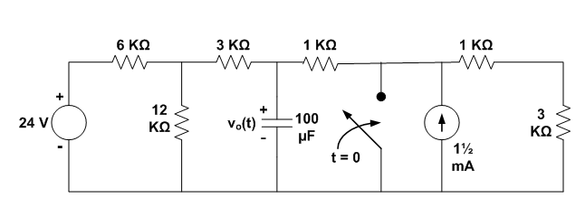
Question (7)
The switch in the circuit shown in figure has been opened a long time before closing at t=0. Using the “Laplace Transform”, derive an expression for the voltage vo(t) for t>0 . Calculate its initial and steady-state values and check your results using the initial and final value theorems.
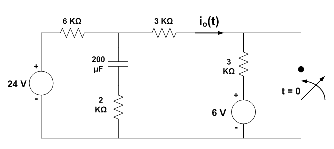
Question (8)
The switch in the circuit shown in figure is closed at t=0 after being opened for a long time. Using the “Laplace Transform”, find the time domain expression for the current io(t) for t > 0 and sketch your results in amperes against time in seconds. Calculate the initial and steady-state values of io(t) using the initial and final value theorems.
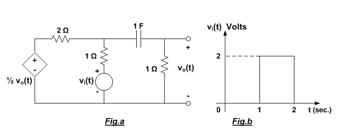
Question (9)
Calculate the output voltage vo(t) for t > 0 in the network shown in Fig.a if the input voltage signal vi(t) is that shown in Fig.b.
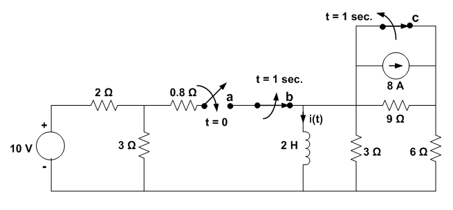
Question (10)
In the circuit shown in figure, switch a was opened, and switches b and c were closed for a long time. At t=0, switch a is closed and after 1 second, switches b and c are opened simultaneously. Determine the expression for the inductor current i(t) that is valid for the periods 0 ≤ t ≤ 1 sec. and t ≥ 1 sec.